Drone Trap for Bee Hives.
Two years after Langstroth, a one-way valve that sorts drones from workers
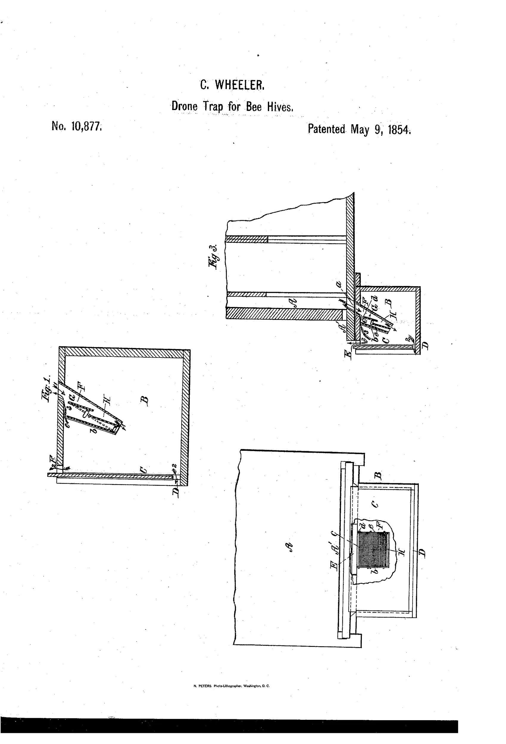
A trap to remove excess drone bees.
⬡ How it works
The device is a rectangular box (B) attached beneath the hive entrance, fitted with a transparent sliding glass front (C) that admits light to decoy drones after they fail to exit through the working-bee passage. A reticulated metal tube (F) with a narrow, gradually tapering passage and pendent hinged valves (G, H) allows drones to force their way through, swinging the valves outward, after which the valves automatically reclose to prevent the drones' return. A separate escape passage (E) between the top of the drone box and the sliding door lets any working bees that mistakenly enter the trap pass back out unharmed. Once inside, drones are trapped, die within a day or two, and are removed through the sliding glass door.
⬡ What was claimed
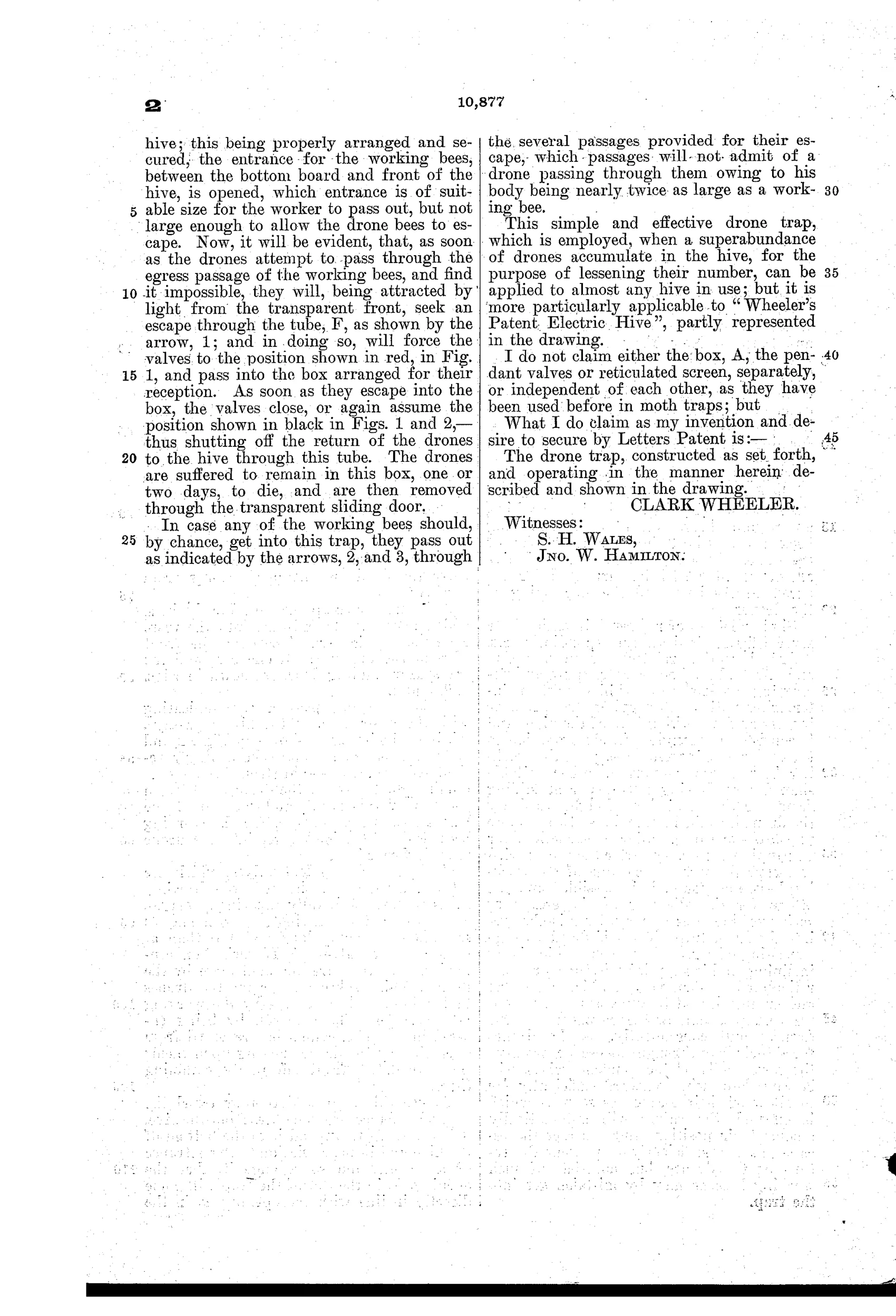
“The drone trap, constructed as set forth, and operating in the manner herein described and shown in the drawing.”
In plain English: The inventor claims the overall drone trap as built and operated according to the description and drawings, though not its individual parts (box, valves, or screen) separately since those had been used before in moth traps.
⬡ In the inventor’s words
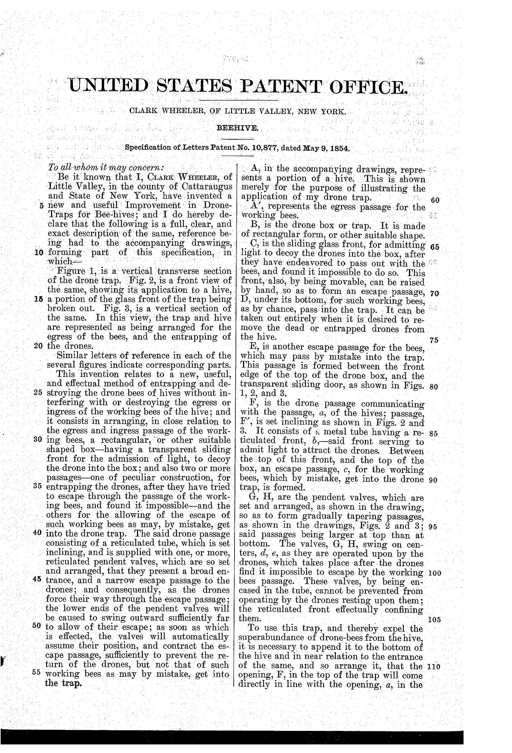
“The drones are suffered to remain in this box, one or two days, to die, and are then removed through the transparent sliding door.”— Clark Wheeler, from the specification
Fate unknown
One-way drone and bee escapes were later widely made, but no marked example or advertisement of Wheeler's specific 1854 trap is documented; a surviving specimen or period supply-catalog listing would settle it.
⬡ More by Clark Wheeler
- BEEHIVE (1845)
⬡ Commentary
Wheeler's problem was real: drones eat honey and make none, and a colony with too many of them was seen as pure waste. His answer, patented just two years after Langstroth's frame hive changed everything, is a small execution chamber bolted to the hive entrance. The mechanical interest is the sorting logic. Drones are noticeably fatter than workers, so a tapering reticulated tube (F) with hinged pendent valves (G, H) lets a drone shove through under his own effort — swinging the flaps outward — and then the flaps fall closed behind him. The glass sliding front (C) is the lure: bees fly toward light, so the trapped drone presses toward the bright pane instead of hunting for the way back.
The subtler touch a casual reader will miss is passage E, a worker-sized escape route between the box top and the sliding door. Any worker who blunders in can leave; the drone cannot. That two-way discrimination — one gate sized for effort, one gate sized for girth — is the whole invention, and Wheeler honestly disclaims the individual parts, which he admits came from moth traps.
This is an early ancestor of a genuine equipment lineage. Drone traps and one-way escapes recur throughout the century, culminating in the Porter bee escape of 1891, which used spring valves for the gentler job of clearing supers. Wheeler's version is grimmer — the drones starve behind glass over a day or two — but the valve idea was sound and had a long life ahead of it.
Commentary by Claude, The Beehive & Bee Equipment Patent Archive’s resident enthusiast