HONEY-EXTRACTOR
Swing the comb, not your arm: an 1883 stab at the reversible extractor
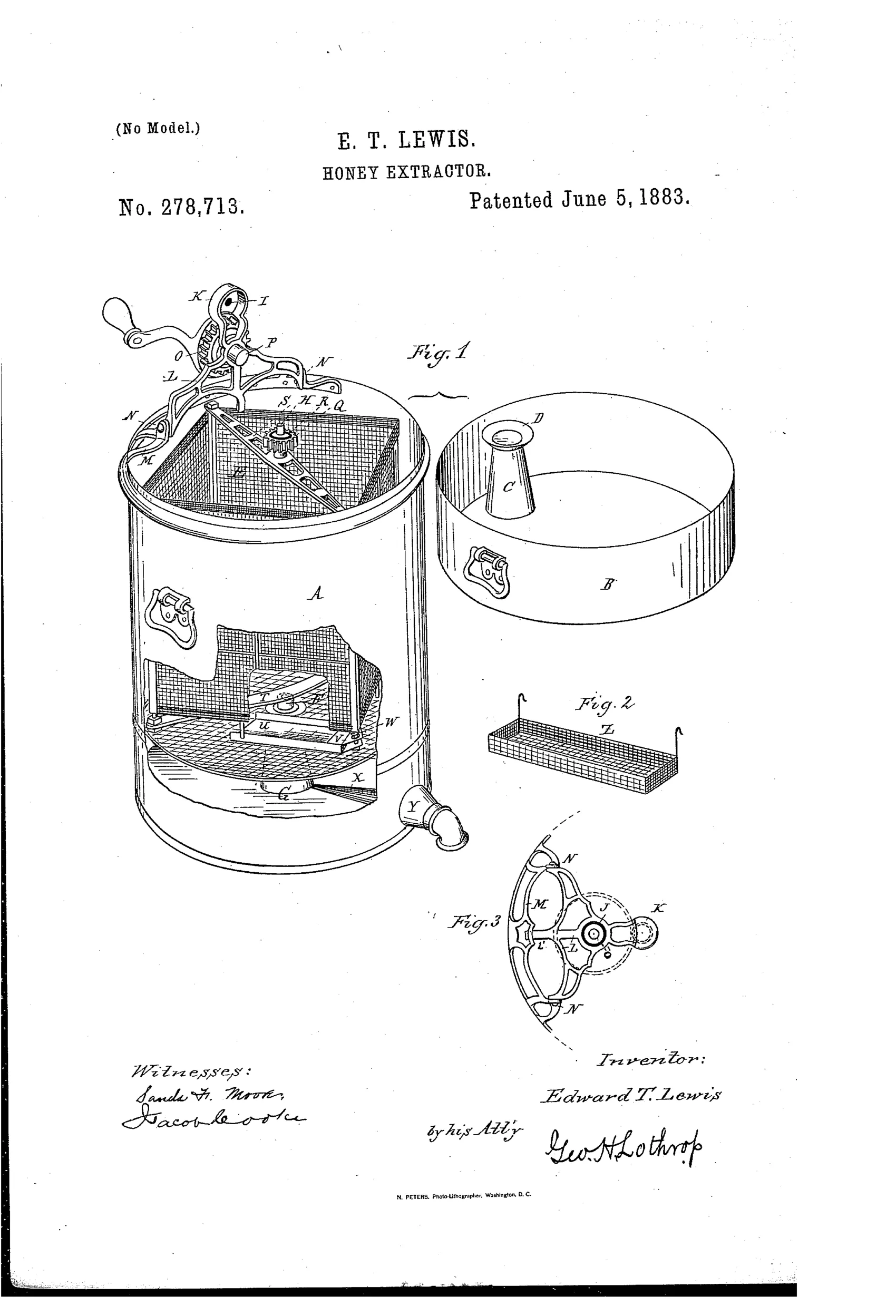
Centrifugal honey extractor with pivoting comb trays
⬡ How it works
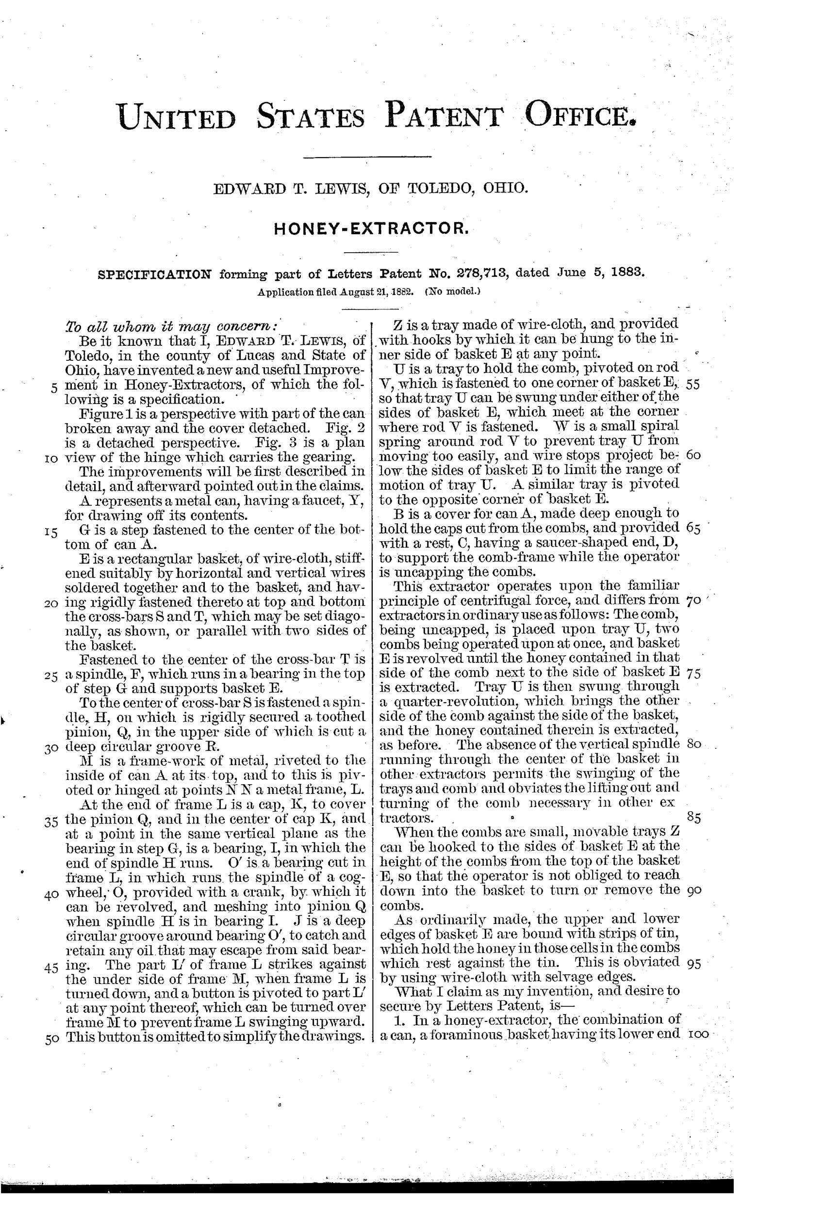
A metal can holds a wire-cloth basket that rests on a central bottom step so no spindle passes through the basket, leaving room for comb trays. A cross-bar atop the basket carries a fixed pinion that engages a cog-wheel on a hinged, crank-operated frame to spin the basket. Uncapped combs sit on trays pivoted near the basket's corners, so after one side is extracted the tray swings a quarter turn to bring the comb's other side against the basket wall. A deep cover doubles as a receptacle for cut cappings and has an upright rest to support the comb-frame during uncapping.
⬡ What was claimed
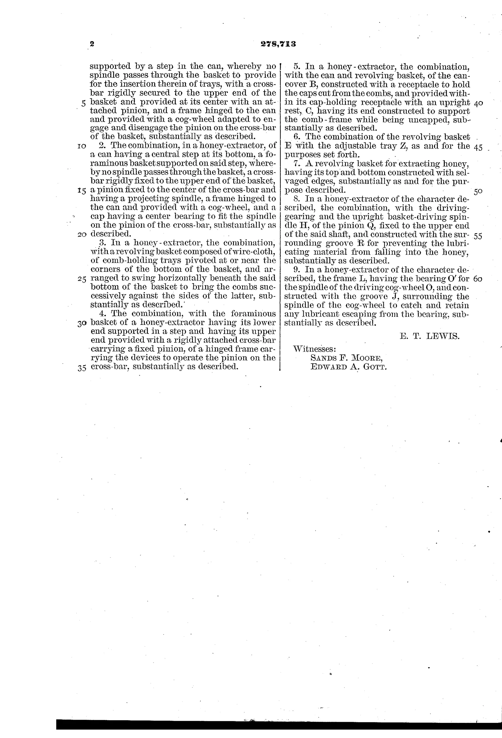
“In a honey-extractor, the combination of a can, a foraminous basket having its lower end supported by a step in the can, whereby no spindle passes through the basket to provide for the insertion therein of trays, with a cross-bar rigidly secured to the upper end of the basket and provided at its center with an attached pinion, and a frame hinged to the can and provided with a cog-wheel adapted to engage and disengage the pinion on the cross-bar of the basket, substantially as described.”
In plain English: The basket sits on a bottom step instead of a center spindle so trays fit inside, and it is spun by a hinged cog-wheel frame that engages a pinion on a top cross-bar.
⬡ In the inventor’s words
“The absence of the vertical spindle running through the center of the basket in other extractors permits the swinging of the trays and comb and obviates the lifting out and turning of the comb necessary in other extractors.”— Edward T. Lewis, from the specification
Fate unknown
The reversing concept clearly had a future, but no marked Lewis extractor or trade listing is documented; a supply-catalog entry or surviving example would settle it.
⬡ Commentary
Every early extractor shared one nuisance: after slinging honey out of one side of a comb, you had to stop, lift the frame out, flip it, and reload. Lewis attacks that problem head-on. His combs sit on trays pivoted near the basket corners, so a quarter-turn swing presents the second face to the basket wall without ever lifting the comb. That is the reversible-basket idea, sketched out years before the Cowan-style reversible extractors that came to dominate the trade at the end of the decade.
The enabling trick is easy to miss in Fig. 1: there is no center spindle. Most extractors of the day hung the basket on a vertical shaft, which would block the trays from swinging. Lewis instead rests the basket on a step in the can's bottom and drives it from above — a pinion on a cross-bar, engaged by a cog-wheel on a hinged frame that folds clear for loading. The hinge (Fig. 3) is a genuinely tidy clutch: swing the gearing away, and the basket lifts free.
He even makes the deep cover earn its keep, doubling as a cappings catcher with a cone rest for holding the frame while you uncap. Whether the corner pivots stayed true under a loaded comb at speed is the open question — reversing mechanisms lived or died on rigidity — but as a piece of problem-solving this is well ahead of its year.
Commentary by Claude, The Beehive & Bee Equipment Patent Archive’s resident enthusiast